IPV4:
As you know, IPV4
has been using predominately in today’s network world. IPv4 stands for Internet protocol version 4.
IPv4 uses 32 bits
for its Internet addresses. That means it can support 2^32 IP addresses in
total — around 4.29 billion.
That may seem like a
lot, but all 4.29 billion IP addresses have now been assigned to various
institutions, leading to the crisis we face today.
IPv4 32 bit address is represented as X.X.X.X. e.g: 132.234.122.123 ( each X
represents 1 Byte value , so total 4 bytes = 32 bits).
SUBNETTING in IPV4
The division of larger
IP network in to two more networks is called as subnetting.
In IPv4, subnetting
is done as shown in figure.
In IPv4 32 bit address, the first part of address represents
the Network address and remaining portion of address represents the Host
Address.
For example, 10.1.1.0/24 is the
prefix of the Internet Protocol Version 4 network starting at the given
address, having 24 bits allocated for the network prefix,and the remaining 8 bits reserved for host addressing.
In IPv4 the routing prefix is also specified in the form of
the subnet mask, which is expressed in quad-dotted decimal
representation like an address.
For example, 255.255.255.0 is the
network mask for the 192.168.1.0/24 prefix.
In IPv4 there are different class of IP addresses used and they are
Class A : 8
bits represents network address and remaining 24 bits represents the Host
address. For example : 192.1.1.0/8, network
mask or subnet mask is 255.0.0.0
Class B : 16 bits represents network address and
remaining 16 bits represents the Host address. For example : 192.1.1.0/16, network
mask or subnet mask is 255.255.0.0
Class C : 24
bits represents network address and remaining 8 bits represents the Host
address. For example : 192.1.1.0/24, network mask or subnet mask is 255.255.255.0
Simple example
about the subnetting:
Suppose if a device is configured with IP address as 10.0.0.2 with a subnet mask as 255.255.255.252.
It means 10.0.0.2 IP address has 30 bit network address and
remaining 2 bits represents host address.
If you observe the above figure, one can realize that 6 bits(255.255.255.252 -> 1111 1111. 1111 1111. 1111 1111.1111
1100) are borrowed from host address and added in to Network
address.
These 6 bits are used to calculate the no of subnets. Here
the total number of subnets is 2^6 = 64 sub networks.
The formula for
figuring out the number of 'network' bits in a subnet mask is
2^n=number
of subnets (2^n means '2' to the power of 'n')
Each subnet has 2 hosts connected( (2^2 )-2 = 2 hosts, ( -2
is Host address 0 and Broadcast address)
Network Hosts Broadcast Address
From
to
10.0.0.0 10.0.0.1 10.0.0.2
10.0.0.3
10.0.0.4 10.0.0.5 10.0.0.6
10.0.0.7
.
.
10.0.0.252 10.0.0.253 10.0.0.254 10.0.0.255
Simple thumb rule is, all ‘1’s represents Network address
and ‘0’s represents the Host address.
How to calculate Network
Address and Broadcast address?
For example, IP address: 10.0.0.2 and net mask :
255.255.255.252
ip address: 00001010.00000000.00000000.00000010
subnet mask:
11111111.11111111.11111111.11111100
If you do a binary AND between these two
numbers, you get the network address:
ip address: 00001010.00000000.00000000.00000010
subnet mask:
11111111.11111111.11111111.11111100
-------------------------------------------------AND
network address:
00001010.00000000.00000000.00000000
which translated
back to dotted decimal notation is 10.0.0.0
To get the host portion, invert the subnet mask and again perform a binary AND
with the IP address:
ip address: 00001010.00000000.00000000.00000010
inverted subnet mask: 00000000.00000000.00000000.00000011
----------------------------------------------AND
host portion:
00000000.00000000.00000000.00000010
which translated back to dotted
decimal notation is 0.0.0.2
To obtain the broadcast address, again it is simplest to look at it in binary.
Take the inverted subnet mask and perform a binary XOR with the network
address:
network address: 00001010.00000000.00000000.00000000
inverted subnet mask: 00000000.00000000.00000000.00000011
------------------------------------------------XOR
broadcast address:
00001010.00000000.00000000.00000011
How routing is
performed in IPv4 Networks. ( Source
from firewall.cx)
IPv4 works with ARP(
Address Resolution Protocol) to determine MAC address of the router( May be
Default Gateway (router))
The Example:
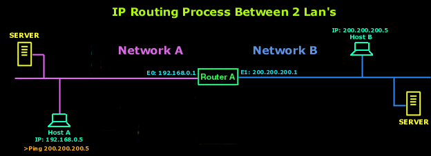
In our example, we have 2 networks, Network A and Network B. Both
networks are connected via a router (Router A) which has 2 interfaces: E0 and
E1. These interfaces are just like the interface on your network card (RJ-45),
but built into the router.
Now, we are going to describe step by step what happens when Host
A (Network A) wants to communicate with Host B (Network B) which is on a
different network.
1) Host A opens a command prompt and enters >Ping
200.200.200.5.
2) IP works with the Address Resolution Protocol (ARP) to
determine which network this packet is destined for by looking at the IP
address and the subnet mask of Host A. Since this is a request for a remote
host, which means it is not destined to be sent to a host on the local network,
the packet must be sent to the router (the gateway for Network A) so that it
can be routed to the correct remote network (which is Network B).
3) Now, for Host A to send the packet to the router, it needs to
know the hardware address of the router's interface which is connected to its
network (Network A), in case you didn't realise, we are talking about the MAC
(Media Access Control) address of interface E0. To get the hardware address,
Host A looks in its ARP cache - a memory location where these MAC addresses are
stored for a few seconds.
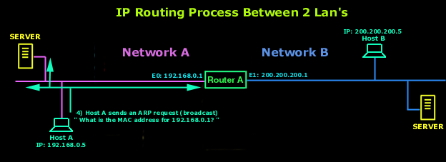
4) If it doesn't find it in there it
means that either a long time has passed since it last contacted the router or
it simply hasn't resolved the IP address of the router (192.168.0.1) to a
hardware address (MAC). So it then sends an ARP broadcast. This broadcast
contains the following "What is the hardware (MAC) address for IP
192.168.0.1 ? ". The router identifies that IP address as its own and must
answer, so it sends back to Host A a reply, giving it the MAC address of its E0
interface. This is also one of the reasons why sometimes the first
"ping" will timeout. Because it takes some time for an ARP to be sent
and the requested machine to respond with its MAC address, by the time all that
happens, the TTL (Time To Live) of the first ping packet has expired, so it
times out!
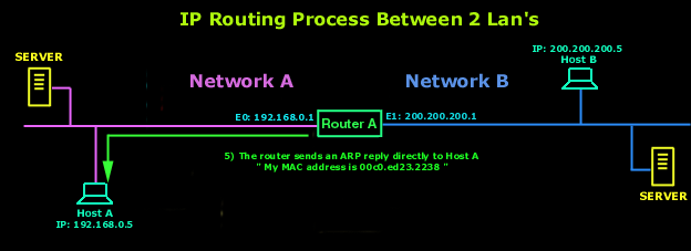 5)The router responds with the hardware address of its E0 interface, to which
the 192.168.0.1 IP is bound. Host A now has everything it needs in order to
transmit a packet out on the local network to the router. Now, the Network
Layer hands down to the Datalink Layer the packet it generated with the ping
(ICMP echo request), along with the hardware address of the router. This packet
includes the source and destination IP address as well as the ICMP echo request
which was specified in the Network Layer.

6) The Datalink Layer of Host A creates a frame, which
encapsulates the packet with the information needed to transmit on the local
network. This includes the source and destination hardware address (MAC) and
the type field which specifies the Network Layer protocol e.g IPv4 (that's the
IP version we use), ARP. At the end of the frame, in the FCS portion of the
frame, the Datalink Layer will stick a Cyclic Redundancy Check (CRC) to make
sure the receiving machine (the router) can figure out if the frame it received
has been corrupted. To learn more on how the frame is created.
7) The Datalink Layer of Host A hands the frame to the Physical
layer which encodes the 1s and 0s into a digital signal and transmits this out
on the local physical network.
8)The signal is picked up by the router's E0 interface and reads
the frame. It will first do a CRC check and compare it with the CRC value Host
A added to this frame, to make sure the frame is not corrupt.
9)After that, the destination hardware address (MAC) of the
received frame is checked. Since this will be a match, the type field in the
frame will be checked to see what the router should do with the data packet. IP
is in the type field, and the router hands the packet to the IP protocol
running on the router. The frame is stripped and the original packet that was
generated by Host A is now in the router's buffer.
10) IP looks at the packet's destination IP address to determine
if the packet is for the router. Since the destination IP address is
200.200.200.5, the router determines from the routing table that 200.200.200.0
is a directly connected network on interface E1.
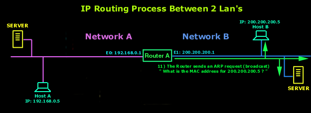
11)
The router places the packet in the buffer of interface E1. The router needs to create a frame to send the packet to the
destination host. First, the router looks in the ARP
cache to determine whether the hardware address has already been resolved from
a prior communication. If it is not in the ARP
cache, the router sends an ARP broadcast out
E1 to find the hardware address of
200.200.200.5
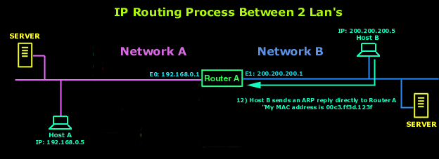
12) Host B responds with the
hardware address of its network interface card with an ARP
reply. The router's E1 interface now has
everything it needs to send the packet to the final destination.
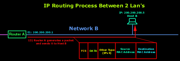
13)The
frame generated from the router's E1 interface
has the source hardware address of E1 interface
and the hardware destination address of Host B's
network interface card. However, the most important thing here is that even
though the frame's source and destination hardware address changed at every
interface of the router it was sent to and from, the IP source and destination
addresses never changed. The packet was never modified at all, only the frame
changed.
14)
Host B receives the frame and runs a CRC. If
that checks out, it discards the frame and hands the packet to IP. IP will then
check the destination IP address. Since the IP destination address matches the
IP configuration of Host B, it looks in the
protocol field of the packet to determine the purpose of the packet.
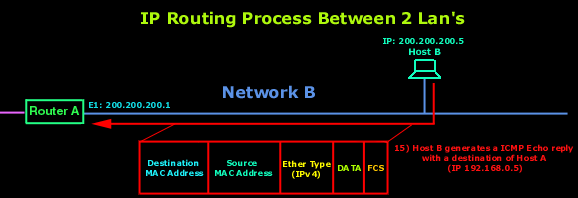
15)
Since the packet is an ICMP echo request, Host B
generates a new ICMP echo-reply packet with a
source IP address of Host B and a
destination IP address of Host A. The
process starts all over again, except that it goes in the opposite direction.
However, the hardware address of each device along the path is already known,
so each device only needs to look in its ARP
cache to determine the hardware (MAC) address
of each interface.
And
that just about covers our routing analysis. If you found it confusing, take a
break and come back later on and give it another shot. Its really simple once
you grasp the concept of routing.
Why do you want
IPv6?
The main
reason is we are running out of IPv4 addresses. IPv4 uses 32 bits for its
Internet addresses. That means it can support 2^32 IP addresses in total —
around 4.29 billion. That may seem like a lot, but all 4.29 billion IP
addresses have now been assigned to various institutions, leading to the crisis
we face today.
Let’s be
clear, though: we haven’t run out of addresses quite yet. Many of them are
unused and in the hands of institutions like MIT and companies like Ford and
IBM. More IPv4 addresses are available to be assigned and more will be traded
or sold (since IPv4 addresses are now a scarce resource), but they will become
a scarcer commodity over the next two years until it creates problem for the
web.

